

How To Fix Charging Port Iphone 7

-
Before you begin, discharge your iPhone battery below 25%. A charged lithium-ion battery can catch fire and/or explode if accidentally punctured.
-
Power off your iPhone before beginning disassembly.
-
Remove the two 3.4 mm pentalobe screws on the bottom edge of the iPhone.
-
Opening the iPhone's display will compromise its waterproof seals. Have replacement seals ready before you proceed past this step, or take care to avoid liquid exposure if you reassemble your iPhone without replacing the seals.

-
Heating the lower edge of the iPhone will help soften the adhesive securing the display, making it easier to open.
-
Use a hairdryer or prepare an iOpener and apply it to the lower edge of the iPhone for about a minute in order to soften up the adhesive underneath.


-
Attach a suction cup to the lower half of the display assembly, just above the home button.
-
Be sure the suction cup does not overlap with the home button, as this will prevent a seal from forming between the suction cup and front glass.
-
If your display is badly cracked, covering it with a layer of clear packing tape may allow the suction cup to adhere. Alternatively, very strong tape may be used instead of the suction cup. If all else fails, you can superglue the suction cup to the broken screen.


-
Pull up on the suction cup to create a small gap between the display assembly and the rear case.
-
Insert the flat end of a spudger into the gap.
-
The watertight adhesive holding the display in place is very strong, and creating this initial gap takes a significant amount of force. If you're having a hard time opening a gap, rock the screen up and down to weaken the adhesive until you can fit a spudger inside.


-
Slide the spudger to the left along the lower edge of the iPhone.
-
Twist the spudger to widen the gap between the display and rear case.


-
Slide the spudger up the left side of the iPhone, starting at the lower edge and moving towards the volume control buttons and silent switch.
-
Do not pry along the top edge of the phone, you risk damaging the plastic clips securing the display.


-
Insert the flat edge of a spudger into the bottom right corner of the device.
-
Twist the spudger to widen the gap between the display assembly and the rear case.
-
Slide the flat end of the spudger up the right side of the phone to break up the adhesive holding the display in place.
-
Do not insert the spudger further than the adhesive to avoid damaging delicate ribbon cables along the right edge.


-
Pull up on the suction cup to lift up the display and open the iPhone.
-
Do not raise the display more than 10º as there are ribbon cables along the right edge of the device connecting the display to the logic board.

-
Pull up on the small nub on the suction cup to remove it from the front panel.


-
Slide an opening pick along the top edge of the iPhone, between the rear case and front panel, to break up the remaining adhesive holding the screen in place.
-
Be careful not to damage the plastic clips on the top edge of the phone.


-
Pull the display assembly slightly away from the top edge of the phone to disengage the clips holding it to the rear case.
-
Open the iPhone by swinging the display up from the left side, like the back cover of a book.
-
Don't try to fully separate the display yet, as several fragile ribbon cables still connect it to the iPhone's logic board.
-
Remove four tri-point Y000 screws securing the lower connector bracket, of the following lengths:
-
Three 1.2 mm screws
-
One 2.4 mm screw
-
Throughout this repair, keep track of each screw and make sure it goes back exactly where it came from to avoid damaging your iPhone.

-
Remove the lower connector bracket.


-
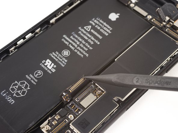
Use the point of a spudger to lift the battery connector out of its socket on the logic board.
-
Bend the connector cable up slightly to prevent it from making contact with the socket and providing power to the phone.


-
Make sure the battery is disconnected before you disconnect or reconnect the cables in this step.
-
Use a spudger or a fingernail to disconnect the two lower display connectors by prying them straight up from their sockets on the logic board.
-
To reconnect these cables, press down on one end until it clicks into place, then repeat on the opposite end. Do not press down on the middle. If the connector is even slightly misaligned, the connector can bend, causing permanent damage.
-
If you have a blank screen, white lines on the display, or partial or complete lack of touch response after reassembling your phone, try disconnecting and carefully reconnecting both of these cables and make sure they are fully seated.


-
Remove the two 1.3 mm Phillips #000 screws securing the bracket over the front panel sensor assembly connector.
-
Some phones could be Y000. Apple started using Y000 for these at some point in the middle of the product's lifecycle.


-
Disconnect the front panel sensor assembly connector from its socket on the logic board.
-
This press connector should also be reconnected one end at a time to minimize the risk of bending.

-
Remove the display assembly.
-
During reassembly, pause here if you wish to replace the adhesive around the edges of the display.

-
Remove the two 1.9 mm Phillips screws securing the barometric vent to the rear case.


-
Remove the vent.


-
Use the flat end of a spudger to disconnect the Taptic Engine connector from its socket on the logic board.

-
Remove the three 1.6 mm Phillips screws securing the Taptic Engine to the rear case.


-
Remove the Taptic Engine.

-
Remove the Phillips screw securing the Wi-Fi diversity antenna to the rear case:
-
One 3.2 mm screw

-
Remove the following three Phillips screws securing the speaker to the rear case:
-
Two 1.3 mm screws
-
One 2.0 mm screw


-
Use the point of a spudger to lift the two antenna cable connectors up off of the sockets on the logic board.


-
Use tweezers to derout the antenna cables from their bracket on the logic board.


-
Use tweezers to remove the antenna cables from the clip on the speaker.
-
Make sure to grasp the cable near the clip in order to avoid damaging the cable.


-
Use the tip of a spudger to slide the speaker assembly towards the logic board and off of the rear case.

-
Remove the speaker.

-
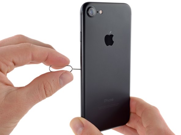
Insert a SIM card eject tool or a paperclip into the small hole in the SIM card tray.
-
Press to eject the tray.
-
This may require a significant amount of force. However, ensure the eject tool is properly aligned beforehand as to not damage the eject mechanism inside the phone.
-
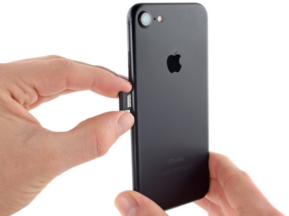
Remove the SIM card tray assembly from the iPhone.
-
When reinserting the SIM card, ensure that it is in the proper orientation relative to the tray.


-
Use the flat end of a spudger to disconnect the rear-facing camera connector.


-
Remove the following Phillips screws securing the rear camera bracket to the rear case:
-
One 1.3 mm screw
-
One 2.5 mm screw

-
Remove the bracket.


-
Use the pointed end of a spudger to pry up and disconnect the antenna bus connector, just left of the rear camera module.

-
Remove the two 1.2 mm tri-point screws securing the upper cable bracket.


-
Remove the upper cable bracket.


-
Use the flat end of a spudger to disconnect the upper cable connector.


-
Remove the four Phillips screws securing the Wi-Fi antenna:
-
Three 1.2 mm screws
-
One 1.7 mm screw


-
Remove the top left antenna.

-
Remove the following Phillips screws:
-
One 1.3 mm screw
-
One 2.2 mm screw


-
Remove the bracket.

-
Remove the 2.2 mm standoff screw from the grounding bracket.
-
Standoff screws are best removed using a standoff screwdriver or bit.
-
In a pinch, a small flathead screwdriver will do the job—but use extra caution to ensure it doesn't slip and damage surrounding components.


-
Use tweezers to gently bend the logic board grounding bracket out of the way.

-
Use the point of a spudger to disconnect the lower cable connector.

-
Remove the following screws:
-
One 1.4 mm Phillips screw
-
Three 2.2 mm standoff screws
-
Standoff screws are best removed using an [linked product missing or disabled: IF145-343-1] and driver handle.
-
In a pinch, a small flathead screwdriver will do the job—but use extra caution to ensure it doesn't slip and damage surrounding components.


-
Use the point of a spudger to move the SIM card eject plunger out of the logic board's way.

-
Use the flat end of a spudger to gently lift the battery connector end of the logic board up.
-
Make sure you're not pulling against any cables. If you feel resistance, check all cables, connectors, and components are clear of the board.


-
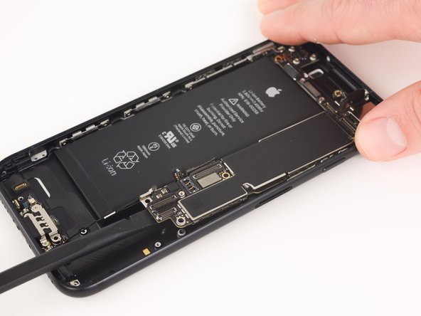
Lift the battery connector end of the logic board and pull it up and out of the rear case.
-
Be careful not to snag the logic board on any cables.

-
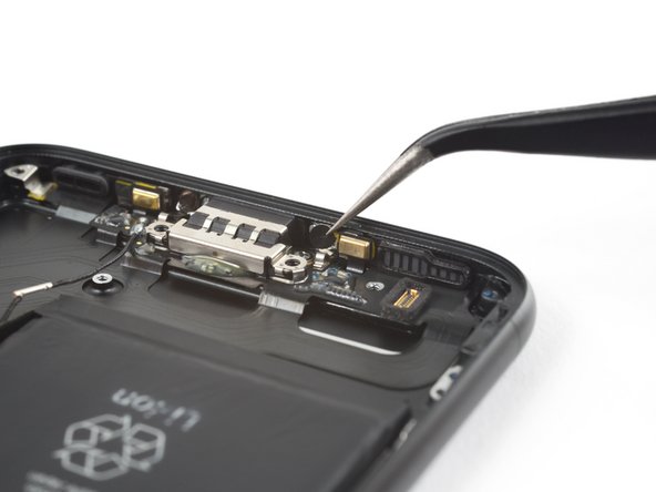
Remove the 2.9 mm Phillips screw from the lightning connector.


-
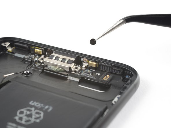
Remove the spring contact from the lightning connector.

-
Remove the two 1.6 mm Phillips screws securing the lightning connector cable in place.

-
Remove the two stickers covering the screws that secure the lightning connector to the bottom of the rear case.

-
Remove the two 1.3 mm Phillips screws from the rear case.


-
Use the pointed end of a spudger to separate the two microphones from the bottom of the rear case.

-
Heating the lower edge of the iPhone will help soften the adhesive securing Lightning connector cable, making it easier to remove.
-
Use a hairdryer or reheat your iOpener to heat the lower edge of the phone.
-
Wait for about a minute, allowing the adhesive to warm up before proceeding to the next step.

-
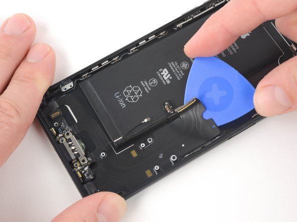
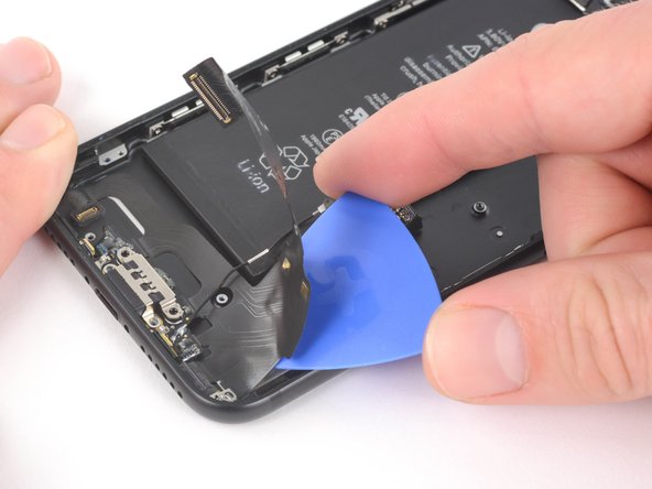
Starting from the middle of the phone, slide an opening pick underneath the lightning connector to separate it from the rear case.


-
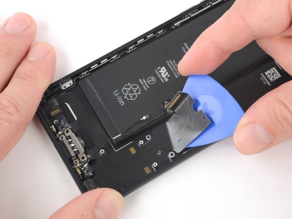
Continue to slide the pick towards the lightning connector to further separate the assembly from the rear case.

-
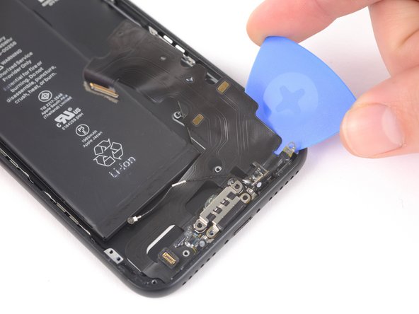
Continue to slide the pick underneath the lightning connecter assembly.
-
Stop sliding the pick once it passes the battery.

-
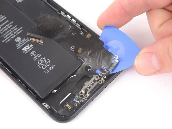
Starting at the corner of the phone, slide the pick underneath the assembly towards the lightning connector.
-
Stop sliding the pick when it reaches the lightning connector.


-
Gently pull the lightning connector out of its hole on the rear case.


-
Slide a pick below the lightning connector to further separate the lightning connector assembly from the rear case.
-
Continue to slide the pick until the lightning connector assembly is no longer adhered to the rear case.


-
Remove the lightning connector assembly.
-
Before installing or replacing the Lightning connector assembly:
-
Use a plastic tool to scour any bits of adhesive residue from the rear case.
-
Make sure the Lightning connector assembly is correctly positioned so that the two white dots on the iPhone's rear case show through the two circular cutouts in the Lightning flex cable. If they don't, the flex cable will remain misaligned and you won't be able to reconnect it to its socket on the logic board.


-
A rubber gasket on the bottom of the Lightning connector protects your iPhone from liquid and dust intrusion. If you are installing a new Lightning connector assembly, you may need to carefully remove and transfer the gasket to the new part.
-
The small adhesive patch on the bottom of each microphone also protects your iPhone from liquid and dust intrusion. For best results, replace the two adhesive patches before installing your Lightning connector assembly.
How To Fix Charging Port Iphone 7
Source: https://www.ifixit.com/Guide/iPhone+7+Lightning+Connector+Assembly+Replacement/78122
Posted by: wrightrurnins.blogspot.com
0 Response to "How To Fix Charging Port Iphone 7"
Post a Comment